Web edge guiding on a printing press
The head reports edge position to the guide controller, which steers the unwind so the print register stays inside tolerance.

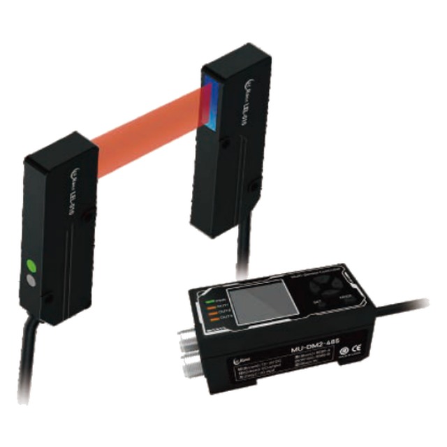
A 660 nm laser through-beam pair that reports edge position across a 5 mm window or strip width across a 10 mm window, with 0.25 µm repeat and a 200 µs sampl
Model MU-DM2-A / MU-DM2-485 + LE-010 · Brand LE Raun · Category: Laser Displacement & Profile
The MU-DM2 is not a distance sensor. It is a shutter: the emitter floods the receiver with a 3 × 14 mm laser band, the material interrupts part of it, and the controller measures how much of the band is covered. That makes the reading independent of the material's colour, gloss or thickness — only the edge position matters.Two evaluation modes come from the same signal. In edge mode the controller reports where the edge sits inside a 5 mm window, which is what a web guide needs. In width mode it reports the full covered width inside a 10 mm window, which is what a slitting line needs. The 485 variant puts the value on a bus so several heads can share one cable run.The head is rated for a mounting distance of up to 300 mm and the linearity figure is quoted at 100 mm, so keep the optics as close to the roller as the machine allows. Temperature drift of ±0.02 % F.S./°C means a cold start in winter will read differently from an afternoon shift — allow a warm-up period before you calibrate.
The head reports edge position to the guide controller, which steers the unwind so the print register stays inside tolerance.
Measures strip width between the knives and flags a drift before the coil is wound out of specification.
Checks that the blank is centred in the press before the ram comes down.
Through-beam geometry does not depend on the surface finish, so it holds on clear film and mirror-finish foil where a triangulation sensor would not.
The edge signal is used to count laps or to follow the outside diameter of a winding coil.
| Controller | MU-DM2-A (analog) · MU-DM2-485 (RS485) |
|---|---|
| Sensor head | LE-010 |
| Light source | Red semiconductor laser, 660 nm |
| Sensor-head mounting distance | Max. 300 mm |
| Measuring range | Edge mode 5 mm · Width mode 10 mm |
| Laser class | Class II (IEC / JIS) |
| Spot size | 3 × 14 mm |
| Linearity accuracy | ±0.2 % F.S. at a mounting distance of 100 mm (25 mm span) |
| Repeat accuracy | 0.25 µm |
| Sampling period | 200 µs |
| Temperature drift | ±0.02 % F.S./°C |
| Indicators | Transmitter power (green) · receiver power (green) · alarm (red) |
| Supply voltage | 10–30 V DC ±10 % |
| Measuring principle | Laser triangulation for short range, time-of-flight for long range |
| Linearity | ±0.1 % F.S. on the precision models |
| Sampling rate | Up to 1 kHz on the fast models |
| Interface | Analogue 4–20 mA / 0–10 V, RS485, or digital switching outputs |
| Protection | IP65 / IP67 aluminium housing |
| Item | Value |
|---|---|
| Emitter / receiver | 42 mm (emitter) / 36.5 mm (receiver) optical depth |
| Cable | 300 mm to M12 4-pin |
| Controller | 76.7 × 28.5 × 17 mm, mounting 18.8 / 36.6 mm, 10.5 mm stand-off |
The head is the 61 mm block that straddles the edge; the controller is the 76.7 mm box that holds the threshold and the output — mount the head on the line and the controller on the frame, 300 mm apart.
| Connection | Function |
|---|---|
| Blue | 0 V |
| Black | Switching output / alarm |
| White | Analogue output (4–20 mA or 0–10 V) |
| Shield | Earth — bond at the controller end only |
Triangulation covers a few millimetres to about a metre with µm resolution; beyond that the time-of-flight models take over at millimetre resolution. Do not ask a 10 mm-range sensor to measure at 500 mm — the spot has already walked off the receiver.
A shiny machined face sends the beam away from the receiver, a black rubber part absorbs it, and a transparent film lets it through. Blue-laser models are the answer for hot, red-glowing or organic surfaces; a 45° mounting removes most mirror reflections.
Analogue for a fast control loop, RS485 when several sensors share one bus or when the reading has to be logged, switching output for a simple go/no-go.
A 1 µm sensor is only as good as its bracket. Thermal growth of an aluminium bracket over 10 °C is more than the repeatability of the sensor; use cast iron, granite or a short, stiff bracket.
The emitter and receiver straddle the material; the controller reports either where the edge sits inside the 5 mm window or how wide the strip is inside the 10 mm window. One mounting, two measurements.
At 200 µs per sample the head keeps up with a web that is moving fast enough to blur a camera — which is the reason through-beam edge sensors still sit on printing and slitting lines.
Splitting sensor head from controller lets the optics be a 20 mm block next to the roller while the terminals, the analog scaling and the RS485 address live in the enclosure.
No. The controller measures the shadow cast on the receiver, so black rubber, white paper and clear film all block the beam the same way. The limit is opacity: a material that lets a significant part of the 660 nm beam through will make the edge look soft.
The -A gives an analog voltage or current proportional to the edge position or width, for a drive or a PLC analog card. The -485 puts the same value on an RS485 bus, which is what you want when several heads sit on one machine and you would rather not run an analog cable to each.
Yes, the mode is a controller setting, not a different sensor head. You cannot read both at the same instant from one controller, but a second controller on the same head type covers the other axis.
Send your application details or the guard opening dimensions and we will specify the right model and configuration for your machine.