Crane and hoist positioning
Measures the distance to a load or a bay wall where a mechanical limit switch would be worn out by the duty cycle.

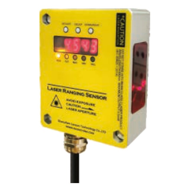
A 658 nm time-of-flight distance sensor with NPN/PNP switching, analog voltage and current outputs and RS485 on the same M12 connector — 1.5 mm + 0.5 % accur
Model LE-TLS-01C-A1 / A2 / A3 / A4 · Brand LE Raun · Category: Laser Displacement & Profile
The LE-TLS-01C measures time of flight: it fires a 2.5 ns pulse at 658 nm and times the return. Because the measurement depends on the round trip and not on the angle of a spot, it works at 4 m and on surfaces that would defeat a triangulation sensor at that distance.Accuracy is quoted as 1.5 mm + 0.5 % of the distance, which is the honest shape of a time-of-flight error: a fixed offset plus a term that grows with range. At 0.5 m the window is under 4 mm; at 4 m it is over 21 mm. The sensor is therefore a positioning and presence device, not a gauging head.The four variants differ only in what is brought out on the M12 lead: switching plus voltage (A1), switching plus current (A2), RS485 (A3) or all three (A4). IP65 and 10–30 V DC supply mean it can be mounted on the machine frame rather than in a cabinet.
Measures the distance to a load or a bay wall where a mechanical limit switch would be worn out by the duty cycle.
Two sensors across a roller table report the dimensions of a plate as it passes, without contact and without a camera.
The 4 m range covers the braking distance of a slow-moving vehicle; the switching output drives the stop directly.
Looks down into a bin and reports the fill height, with the analog output scaled to the vessel.
A 4 ms output time is fast enough for a part on a conveyor to be measured between two stations.
| Model | LE-TLS-01C-A1 / A2 / A3 / A4 |
|---|---|
| Control output | NPN / PNP switching, voltage and current analog output, RS485 output |
| Adjustable range | 0.1 m to 4 m, adjustable |
| Detection accuracy | 1.5 mm + d × 0.5 % |
| Measuring object | Natural targets |
| Light source | Red laser, 658 nm |
| Pulse duration | 2.5 ns |
| Output time | ≥ 4 ms |
| Max. power | 120 mW |
| Supply voltage | 10–30 V DC ±10 % |
| Connection | M12 waterproof connector, cable lead |
| Protection level | IP65 |
| Product application | Detect fast moving objects; measure thickness, length, width and position of plates |
| Measuring principle | Laser triangulation for short range, time-of-flight for long range |
| Typical repeatability | 1 – 10 µm on the triangulation models |
| Linearity | ±0.1 % F.S. on the precision models |
| Sampling rate | Up to 1 kHz on the fast models |
| Interface | Analogue 4–20 mA / 0–10 V, RS485, or digital switching outputs |
| Item | Value |
|---|---|
| Weight | 360 g with the 2 m cable |
| Connection | M12 waterproof connector, flying lead |
| Adjustable range | 0.1 – 30 m, set by the model |
The aluminium body is the heatsink for the 2.1 W laser, so do not wrap it in a plastic bag on a hot line; the PMMA window scratches, and a scratched window shows up as a permanent distance offset.
| Connection | Function |
|---|---|
| Blue | 0 V |
| Black | Switching output / alarm |
| White | Analogue output (4–20 mA or 0–10 V) |
| Shield | Earth — bond at the controller end only |
Triangulation covers a few millimetres to about a metre with µm resolution; beyond that the time-of-flight models take over at millimetre resolution. Do not ask a 10 mm-range sensor to measure at 500 mm — the spot has already walked off the receiver.
A shiny machined face sends the beam away from the receiver, a black rubber part absorbs it, and a transparent film lets it through. Blue-laser models are the answer for hot, red-glowing or organic surfaces; a 45° mounting removes most mirror reflections.
Analogue for a fast control loop, RS485 when several sensors share one bus or when the reading has to be logged, switching output for a simple go/no-go.
A 1 µm sensor is only as good as its bracket. Thermal growth of an aluminium bracket over 10 °C is more than the repeatability of the sensor; use cast iron, granite or a short, stiff bracket.
Time-of-flight works on natural targets, so there is no reflector to mount, clean or lose. Point it at the object and read the distance.
Switching, analog and RS485 are all available from the M12 lead. The A1–A4 variants select which combination is brought out, so the same sensor fits a PLC input, an analog card or a bus.
The error grows with distance, and the datasheet says so. At 1 m the worst case is 6.5 mm; at 4 m it is 21.5 mm. Size the tolerance window accordingly instead of assuming a single number.
No. The beam has to reach the surface. For a closed tank you need a window or an ultrasonic sensor mounted inside; the LE-TLS is specified for a direct line of sight to a natural target.
Because the error has two parts: a fixed offset from the timing electronics and a term proportional to distance from the pulse width and the signal-to-noise ratio. Quoting a single number would be optimistic at 4 m and pessimistic at 0.3 m.
A mirror at normal incidence can return more light than a matt surface, but if it deflects the beam away the sensor sees nothing. Tilt a reflective target by a few degrees, or use a matt tape on the measurement spot.
Send your application details or the guard opening dimensions and we will specify the right model and configuration for your machine.