Robot pick-and-place centring
The part is placed on the pin; X and Y offsets go to the robot as a correction before the gripper closes.

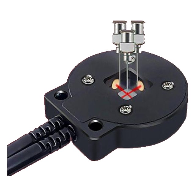
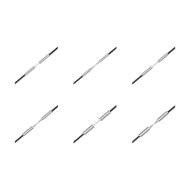
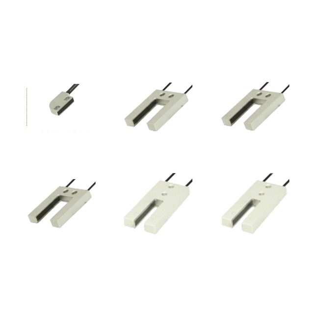
A machined aluminium head with a cross-shaped aperture and four fiber bundles, used as a positioning pin: the part is pushed onto the pin and the four beams
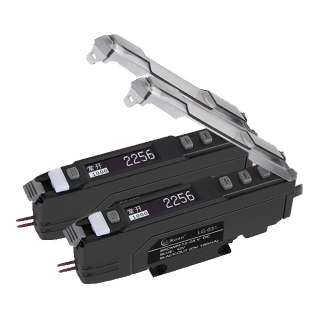
Model LE-XZ3910 (with LE-031 / LE-025 amplifier) · Brand LE Raun · Category: Fiber Optic Sensors
A positioning pin does two jobs at once: it locates the part mechanically and it reports how far the part is from the ideal position. The LE-XZ3910 does the second job with four fiber bundles looking at a cross-shaped aperture — as the part covers the aperture, each bundle sees a different amount of light, and the difference between opposite bundles is the offset.Because the measurement is optical, there is no contact wear on the sensing element: the pin takes the mechanical load, the light does the measuring. That is why the same head is used on a manual load station and on a robot pick-and-place cell.It is specified with an LE series amplifier, which is also the reason the accuracy figure is quoted with a response mode: a 1 ms mode will not resolve an offset that a 60 µs mode sees, if the part is still moving when it is measured.
The part is placed on the pin; X and Y offsets go to the robot as a correction before the gripper closes.
Z from the change in total light: a connector that has not seated fully reads short, and the station stops before the next operation.
Two lamps on the fixture show the operator which way to nudge the part — no screen, no PLC code.
The head doubles as the reference for verifying that a fixture still locates parts within ±0.02 mm after a changeover.
| Type | Positioning-pin fiber sensor head, four fiber bundles to one or two amplifiers |
|---|---|
| Head dimensions | 23 × 39 × 6.8 mm, aluminium |
| Fiber diameter | Ø1.0 mm fiber outer diameter |
| Detection | 0.1 mm |
| Centring accuracy | X axis ±0.02 mm · Y axis ±0.02 mm · Z axis ±0.01 mm |
| Response time | Anti-OFF: 50 µs (HIGH SPEED) / 250 µs (FINE) · 1 ms (SUPER) / 16 ms (MEGA) |
| Sensing mode | Light intensity (area detection, auto sensitivity tracking function) |
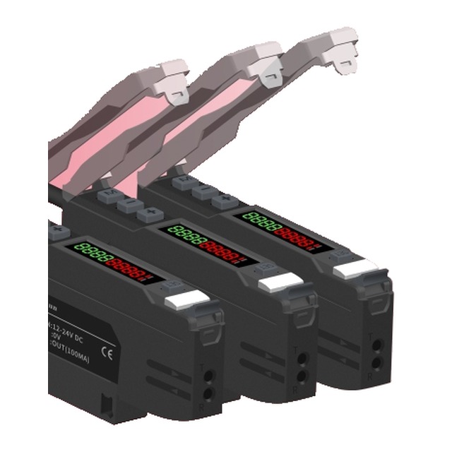
| Amplifier | LE-031 / LE-025 offset-detection amplifier (per the 2026–2027 catalogue) |
| Output | Four switching signals — one per quadrant — or two differential pairs |
| Supply voltage | 12–24 V DC ±10% |
| Item | Value |
|---|---|
| Amplifier | 33.86 (H) × 11.2 (W) × 75 (W) mm — LE-031 / LE-025 offset-detection amplifier |
| Fiber outer diameter | Ø1.0 mm |
| Calibration accuracy | X-axis ±0.02 mm · Y-axis ±0.02 mm · Z-axis ±0.01 mm; detection 0.1 mm |
| Functions | Switching / analog output optional · NO / NC with delay · counting, zero shift, light-interference prevention, area rising/falling-edge mode, percentage, etc. |
The head is a positioning pin, so its own tolerance matters: mount it on a machined face and re-check the pin run-out, not just the head position.
| Bundle | Goes to |
|---|---|
| 2 | Amplifier A, channel 2 |
| 3 | Amplifier B, channel 1 |
| 4 | Amplifier B, channel 2 |
The head is the datum: press the part onto the pin, then route the four bundles with R25 or more. A bundle pulled tight at the head moves the reading.
Two amplifiers give four independent thresholds; one amplifier with two channels handles X only. Most installations use two.
Teach with a good part in place. A pin taught empty has no reference for the ±0.02 mm window.
The Z signal depends on the approach speed — a fast push overshoots. Approach at the speed the machine will use in production when teaching.
X and Y from the four quadrant bundles, Z from the total light as the part seats. A single head replaces three separate sensors and their brackets.
The accuracy comes from the machined aperture, not from the light source, so no laser class and no safety paperwork.
It runs on the LE-031 / LE-025 offset-detection amplifier the catalogue specifies for this head — one spare part covers the whole cell.
Slim enough to sit inside a fixture plate without a cut-out.
The four bundles measure coverage of the aperture, so any part that covers the cross works. A part smaller than the aperture cross will not give a usable Z signal.
Two for a full X/Y reading (four channels), one if only one axis is monitored.
It is the centring accuracy quoted in the catalogue with a seated part and a static measurement. Repeatability depends on the amplifier mode and the approach speed, which is why the mode is part of the specification.
Send your application details or the guard opening dimensions and we will specify the right model and configuration for your machine.